Introduction:
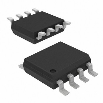
Power management chips are essential components in electronic devices, controlling the distribution and regulation of power to ensure optimal performance and efficiency. These chips typically have multiple pins that serve different functions. In this article, we will discuss the 8 pins commonly found in power management chips and their respective functions.

Pin 1: VIN (Input Voltage)
The VIN pin is where the power management chip receives the input voltage from an external power source. This voltage can vary depending on the device and application, and the chip regulates it to provide a stable output voltage to the rest of the system.
Pin 2: VOUT (Output Voltage)
The VOUT pin is where the regulated output voltage is delivered to the load or other components in the system. The power management chip ensures that the voltage remains within the specified range, even under varying load conditions.
Pin 3: GND (Ground)
The GND pin is the reference point for the voltage levels in the system. It serves as the return path for current flow and helps stabilize the voltage levels across the circuit. Proper grounding is crucial for the overall performance and safety of the device.
Pin 4: Enable (EN)
The Enable pin is used to turn the power management chip on or off. By applying a control signal to this pin, the chip can be activated or deactivated, allowing for power savings and control over the system's power consumption.
Pin 5: Feedback (FB)
The Feedback pin is used to provide feedback to the power management chip about the output voltage. This information is used by the chip to adjust its regulation circuitry and ensure that the output voltage remains stable and within the desired range.
Pin 6: Soft Start (SS)
The Soft Start pin is used to control the ramp-up time of the output voltage when the chip is initially powered on. This feature helps prevent voltage spikes and ensures a smooth and controlled start-up sequence, protecting the components in the system.
Pin 7: Power Good (PG)
The Power Good pin is used to indicate when the output voltage has reached its stable and regulated state. This signal can be used by other components in the system to ensure that they only start operating once the power supply is fully functional and stable.
Pin 8: Overcurrent Protection (OCP)
The Overcurrent Protection pin is used to monitor the current flowing through the power management chip and protect it from damage in case of a short circuit or overload condition. When the current exceeds a certain threshold, the OCP feature will trigger and shut down the chip to prevent damage.
Conclusion:
In conclusion, the 8 pins of a power management chip play crucial roles in regulating and controlling the power supply to electronic devices. Understanding the functions of each pin is essential for designing and implementing power management solutions that are efficient, reliable, and safe. By utilizing these pins effectively, engineers can ensure optimal performance and longevity of electronic systems.

