Editor’s Note: This is the first article in a three-part series about software defined radios in GPS/GNSS simulators.
Part 1: About GPS and various techniques that are used to advance signal technology, satellite systems and signals, architecture and modernization efforts
Part 2: GPS simulators, software defined radio architecture and its integration into simulators
Part 3: Testing using SDRs and GPS signal examples
Global Positioning System (GPS), originally called Navigation System with Timing and Ranging (NAVSTAR), was initially developed as a military navigating system in 1978 and reached full operational capacity in 1993 with 24 satellites in the system. Later on, the next generation GPS III and systems developed by Russia (GLONASS), the Europe Union (Galileo) and China (BeiDou), collectively called GNSS (Global Navigation Satellite Systems) have expanded the potential of satellite navigation worldwide. Satellite navigation has been ingrained in our lives and operations, from applications such as Google Maps, to asset tracking, logistics, landing of aeroplanes etc. that it is impossible to function without it.
Recent developments in GPS and the addition of new constellations have improved the accuracy of PNT (Position Navigation and Timings) using techniques such as Satellite Based Augmentation System (SBAS), Ground Based Augmentation System (GBAS), Differential GNSS (DGNSS), Precision Point Positioning with Real-Time Kinematic positioning (PPP-RTK) and multi constellation receiver. Signal integrity is further enhanced by using anti-spoofing measures such as receiver autonomous integrity monitoring (RAIM), while better continuity is ensured by augmenting GNSS with microelectromechanical systems (MEMS) and low cost inertial navigation system (INS). Most of these advancements have been made possible by improved signal processing techniques in acquisition tracking and position calculation algorithms.
The addition and integration of GNSS receivers into original equipment manufacturer (OEM) equipment and wireless electronics require extensive test and measurement (T&M) and set up during the development and qualification process. In a conventional GPS receiver, the acquisition and tracking of GPS signals are all processed by dedicated hardware. In a software-based GPS receiver or software defined radio (SDR), the signal is digitized using an analog-to-digital converter (ADC). The digitized input signal is then processed using software routines and algorithms. The software can perform typical GNSS functions such as signal acquisition and tracking, navigation data extraction and position calculations and, more importantly, the parameters can be conveniently changed, and the receiver can be adapted to suit different conditions. SDRs have been touted by many as the future of wireless communications and RF solutions.
The application of satellite navigation in various products has increased exponentially and the GNSS based products have become more complex and thus require extensive testing during design, development, and qualification phases under various scenarios and environments.
SDRs are becoming a valuable resource for test and measurement of radiofrequency (RF) device function and capability development. These radio systems are particularly enticing due to their ability to be upgraded via software and/or field-programmable gate array (FPGA) IP cores, and thereby providing T&M engineers with extended flexibility, capabilities, and cost-efficiency. Extensive testing of GNSS based products during design and development phase is imperative, as any errors can be costly to fix and can prove deadly in emergency situations, such as search & rescue. It can be beneficial to include SDR-based GNSS simulators in the testing regime.
All about GPS/GNSS satellite systems and signals
GPS satellite systems are comprised of three segments: the space segment, the control segment, and the user segment. The space segment consists of GPS satellites in semi-synchronous orbits, which are arranged in six orbital planes with four satellites in each plane. The satellites have an average orbit altitude of 20,200 km above the surface of Earth and complete one orbit in approximately 11 hours and 58 minutes. The system is designed so that at least five satellites are visible at any point on the Earth’s surface having a clear view of the sky. Currently, there are 32 NAVSTAR GPS satellites in orbit and the constellation is constantly being replaced and upgraded, with some of the satellites kept as spares for emergency situations.
The ground/control segment consists of ground stations which track satellites, monitor their transmissions, analyze data and communicate with the constellation. This includes monitor stations, master control stations, and ground antennas, which provide timekeeping, integrity, and track transmission, clocks, status, and orbits. The user segment includes all GPS users and consists of receivers specifically designed to receive, decode and process the GPS satellite signals and are found within cell phones and dedicated ground control stations, along with aircraft, ships at sea, and land vehicles in motion.
Each GPS satellite carries several high accuracy atomic clocks and transmits codes that start at precisely known time. In order to make measurements, the GPS employs the concept of time-of-arrival (TOA) ranging to determine user’s position. Measurements are made to calculate the time it takes for a signal transmitted by the satellite/space vehicle (SV) at a known location to reach a user’s receiver. The receiver performs position calculations by measuring the propagation time of signals broadcasted from multiple GPS satellites from known locations. The position of GPS receivers is calculated by trilateration, which is the traditional, simplest, and most accurate method of locating an unknown position.
The GPS consists of two levels of service, the Precise Positioning Service (PPS) and the Standard Positioning Service (SPS). The PPS is an accurate positioning, velocity and timing service only available to authorized users. The SPS, utilizing the Clear/ Acquisition code (C/A-code) is a less accurate navigation service and is primarily intended for civilian applications and is available to all users on L1 frequency.
The GPS satellites transmit two carrier frequencies called L1, the primary frequency at 1575.42 MHz, and L2, the secondary frequency at 1227.6 MHz. The GPS signals are transmitted using direct sequence spread spectrum (DSSS) techniques, employing two different ranging codes used as spreading functions. These codes broadcasted by the satellites enable a GPS receiver to measure the transit time of the signals and thereby determine the distance between a satellite and the user. The navigation message provides data to calculate the position of each satellite at the time of signal transmission. From this information, the user position coordinates and the user clock offset are calculated using appropriate algorithms. Four satellites are normally required to be simultaneously in view for the receiver to solve the equations for three-dimensional positioning purposes.
As part of GPS modernization efforts, several new signals e.g. L1C, L2C and L5 (1176.45 MHz) have been included in the GPS signal in order to increase the accuracy and integrity for all users, while maintaining backward compatibility with existing GPS equipment. The L5 signal is being transmitted at a higher power than current civil GPS signals, and has a wider bandwidth. The C/A code consists of a 1023-bit pseudorandom noise (PRN) sequence with a clock rate of 1.023 MHz that repeats every one millisecond. A different PRN code is assigned to each GPS satellite and selected from a set of two codes called gold codes. Low cross-correlation of the sequence is imperative because the GPS receiver has to simultaneously distinguish among signals from as many as 12 satellites using correlation techniques.
The navigation message contains information used by GPS receivers to optimize the acquisition of satellite signals and performs position calculations and other navigation parameters. The 50 Hz navigation message is superimposed on both the P (Y) code and the C/A code. The narrow bandwidth of the navigation message ensures a high SNR ratio at the demodulator input and correspondingly low probability of bit errors in the navigation message. Each GPS satellite has four atomic clocks that are calibrated against time standards in the GPS control stations around the world. This results in internal reference time used by the three segments in the GPS system and is called GPS time. However, it is not cost effective to place atomic clocks in GPS receivers, thus necessitating the use of standard crystal oscillators. Consequently, the receiver clock has a clock offset with respect to the satellite and results in inaccuracies in position measurements. Fortunately, a time measurement from a fourth satellite helps in solving the receiver clock offset error.
The GNSS includes GPS (USA) and GPS modernization, GLONASS (Russia), Galileo (Europe), BeiDou (China) and various augmentation systems like SBAS, GBAS, QuasiZenth (Japan) etc. The availability of signals from extra satellites improves continuity, accuracy and efficiency of GNSS navigation solutions. Extra satellites and signals can enhance availability of satellites at a particular location and improve reliability. To comprehend the number of satellite navigation signals available, the following is the list of GNSS frequencies that modern receivers like SEPTENTRIO (model AsteRx-m2a UAS) can support; GPS: L1, L2. GLONASS: L1, L2. Galileo: E1, E5b. BeiDou: B1, B2. SBAS: EGNOS, WAAS, GAGAN, MSAS, SDMC (L1) and QZSS: L1, L2. Some of these frequencies for GNSS signals are shown in the following figure:
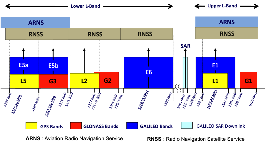
Different frequencies for GNSS signals (Source: Per Vices
GPS and GNSS systems are a crucial part of all applications spanning both commercial and defence. These systems are deployed across a large number of devices resulting in the need to ensure all devices operate as expected prior to deployment. Software defined radios provide a perfect blend of performance and flexibility to help GPS/GNSS manufacturers test existing equipment along with the ability to adapt for testing of new methods across a wide number of frequencies. These SDRs can be used for simulation of RF environments, testing for specific power thresholds and noise for GPS/GNSS transmitters, and for ensuring the receivers designed for GPS/GNSS operate as expected.
 Dr Mohammad Usman did his BE (Electrical Engineering) from University of Engineering and Technology Lahore, Pakistan and MSc and PhD from the University of Manchester, UK. He has more than twenty eight (28) years of experience in the private industry and public sector research organization of Pakistan in the field of electronics design, software development, communications, project management and aerospace product development. His research interests include GNSS (Global Navigation Satellite System) based remote sensing, GPS based bi-static SAR (Synthetic Aperture Radar) and GNSS/GPS signal processing. Dr Mohammad Usman did his BE (Electrical Engineering) from University of Engineering and Technology Lahore, Pakistan and MSc and PhD from the University of Manchester, UK. He has more than twenty eight (28) years of experience in the private industry and public sector research organization of Pakistan in the field of electronics design, software development, communications, project management and aerospace product development. His research interests include GNSS (Global Navigation Satellite System) based remote sensing, GPS based bi-static SAR (Synthetic Aperture Radar) and GNSS/GPS signal processing. |